
Autelo – A Two-Week Journey to a Self-Driving Wheelchair
We are developing the next generation of control systems and interaction elements for motorized wheelchairs. Our collaboration with a drive technology manufacturer sparked our curiosity about the future of self-driving wheelchairs – and they let us take a prototype of their drive system and gently hack it. We also brought in a 360° laser scanner, some electronics, and open-source software from the field of autonomous driving.
We set up a sprint to tackle the technical challenge: two people, two weeks, and a maximum of 2,500 euros for additional hardware. We wanted to highlight what is currently state-of-the-art and what is still in the research phase. The goal wasn’t to find the perfect solution, but rather to perform a reality check: the wheelchair was supposed to autonomously navigate to a destination specified via voice command within a pre-mapped area.
By the end of the two weeks, the wheelchair was navigating independently along a pre-mapped route – on voice command. What didn’t work: navigating completely open areas, mapping runs with rapid changes in direction, and objects below the scanning plane, particularly curbs.
Approach
The goal was to systematically test fundamental technical assumptions in predefined phases so that we could build upon them in the next step:
- Getting to know and stress-testing the drive interface: Latency and range in various environments, dead man's switch timeout value, encoder format.
- SLAM mapping and indoor navigation using a 2D lidar sensor (RPLIDAR), an IMU (Inertial Measurement Unit), and wheel odometry, including targeted interference tests.
- Mapping and navigation in outdoor and urban environments through the additional use of a stereo RGB-D camera and an Nvidia Jetson Orin Nano Developer Kit.
- Creation of a semantic map by linking the geometric positions of semantic objects or locations to the map generated using SLAM, thereby allowing destinations to be defined based on their semantic meaning rather than solely on coordinates. Integration of voice or text commands from wheelchair users for navigation. Processing these commands using a language model that calculates the route in coordination with the navigation system. Development of web-based user interfaces for mapping and navigation to enable “headless” visualization without an additional screen.
The Key: Integration
Almost everything that enables Autelos' autonomy is already available: the navigation software, the mapping, and the sensor drivers. We wrote the adapter between the navigation and the manufacturer's control system ourselves. The rest involved putting things together, testing, refining, or discarding.

„Since our partner's motors and control system are already designed for medical applications, our task was integration: implementing a ROS-2 node that sits between the motion commands sent to the wheels and the control protocol, and that manages and reads the wheel odometry.”
Out of Scope
To achieve a breakthrough within the project timeframe, we have deliberately limited the scope of functionality: no GPS (accuracy is in the meter range under tree canopies and between buildings), no new drive electronics, and no free path planning. Instead, we rely on scan matching based on a map we created ourselves, the drive's ready-to-use wireless interface, and a precise, stable, and reliable navigation algorithm such as “Regulated Pure Pursuit.” However, all of these functions can be adapted or expanded as needed.
Hardware and Software – The System Architecture
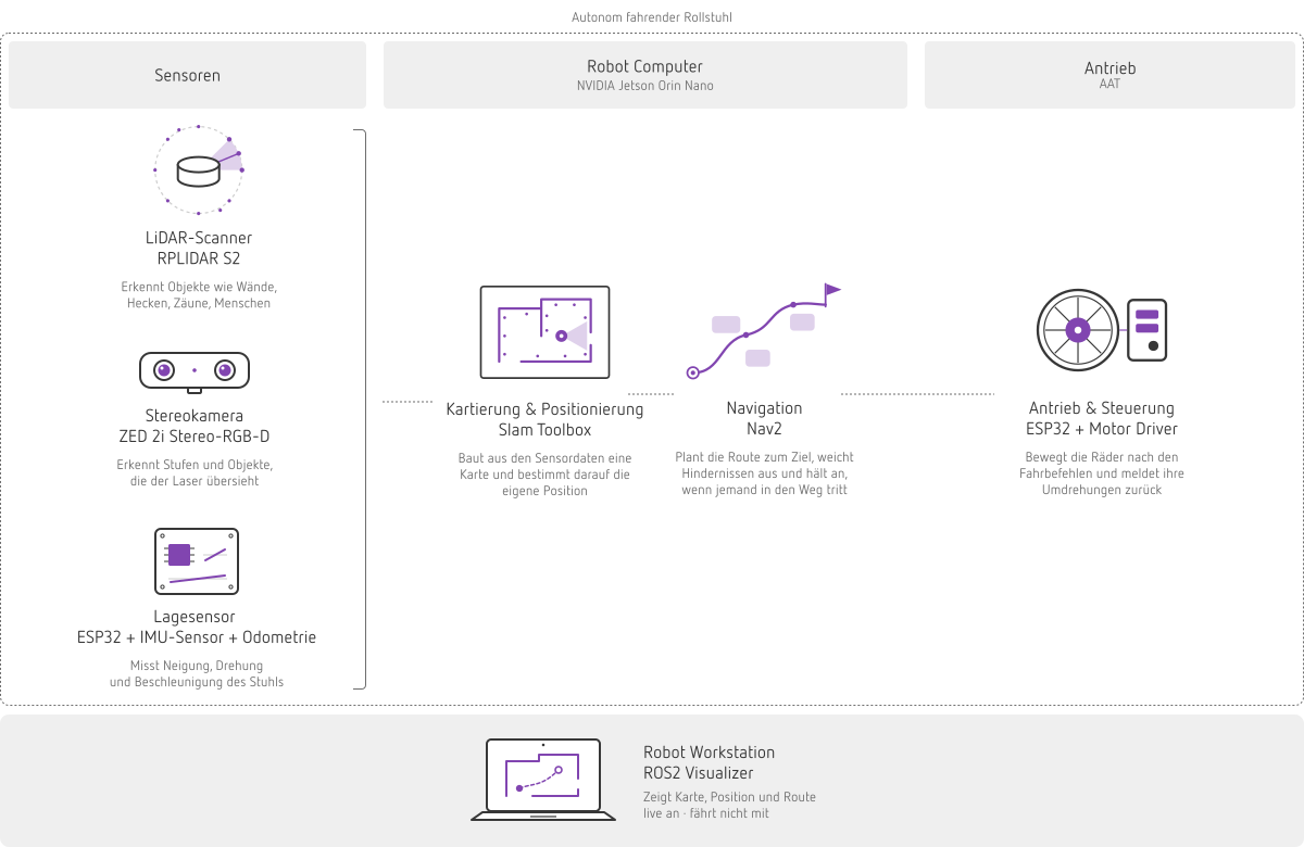
We used the navigation and SLAM mapping algorithms available in ROS2 as the standard foundation for our development work. We programmed all other software ourselves to enable communication between ROS2, the navigation and mapping algorithms, the microcontrollers, the sensor interfaces, and the user applications and interfaces. Below is an overview of the bill of materials and the software stack:
- Drive and control system directly from the manufacturer – wireless interface with dead-man monitoring, encoder feedback
- 2D lidar for SLAM and obstacle avoidance: Slamtec RPLIDAR S2, 360°, 30 m range, IP65 (approx. 427 €)
- Camera for navigation and object detection: Stereolabs ZED 2i stereo RGB-D camera, IP66, 2.1-mm lens (approx. €950)
- IMU breakout board: BNO055 – 9-axis sensor consisting of a 3-axis accelerometer, 3-axis gyroscope, and 3-axis magnetometer; tracks motion, acceleration, and spatial orientation (approx. €25)
- Processor / robot computer: NVIDIA Jetson Orin Nano Super Dev. Kit, 67 TOPS, 8 GB DDR5 – for running slam_toolbox, Nav2, and the rest of the navigation stack (approx. €500)
- Power Supply: DC-DC converter to power auxiliary hardware and the Jetson using the wheelchair battery (approx. €250)
- Middleware: ROS 2 Jazzy on Ubuntu 24.04
- Navigation: Nav2 – Costmap, Planner, Controller, Speed Limit
- Mapping and Localization: slam_toolbox
- Sensor fusion: robot_localization, Extended Kalman Filter (EKF) using wheel odometry and IMU
- LiDAR driver: rplidar_ros
- Mapping runs and manual fallback mode: teleop_twist_joy / teleop_twist_keyboard
- Monitoring: Foxglove Studio / Rviz2
- Specific code: wheelchair_driver_node (Python/rclpy) – translates cmd_vel into the drive's control protocol and encoder values into nav_msgs/Odometry
- Additionally: Mounting hardware for sensors (possibly 3D-printed, approx. 50 €), cables, connectors, fuses, a weatherproof enclosure (approx. 60 €), cones and barrier tape for course marking (approx. 20 €), a dedicated travel router, a gamepad, an additional deadman switch, and a buffer for unforeseen circumstances.
How the Wheelchair Creates the Map
The map is generated during manual operation: slam_toolbox continuously creates a representation of the environment using 360° scans from the RPLIDAR and – optionally – an additional RGB-D camera. Nav2 then uses this map and a scan-matching algorithm for navigation and localization. To determine the precise position and orientation, wheel odometry data and IMU measurements are fused using an Extended Kalman Filter.
How a Map Becomes a Route
During the journey, the navigation algorithm (Nav2) calculates a so-called cost map, in which each detected obstacle defines a safety radius around itself. The path planner determines the “optimal” path through the map, while the control system keeps the wheelchair on that route. Since the route is known, the main task is not free path planning, but rather precisely following the path and avoiding obstacles or objects that suddenly appear along the route.
Reaching Your Destination with Voice Commands
To control the wheelchair using natural language, we employ a language model that accepts spoken or written instructions from users. In addition, we have expanded the geometric map—generated using SLAM—into a semantic map that contains important destinations or objects. The language model identifies these locations or objects based on the voice commands and transmits the corresponding destination coordinates from the semantic map to the navigation system.

Technical Challenges
Several challenging obstacles arose during the course of the project. Here’s a look at what led to these problems and how we addressed them:
Limited accuracy of 2D-SLAM and Nav2 in outdoor environments. As soon as the point cloud scanned by the LiDAR sensor no longer encounters any structures such as hedges, walls, fences, or building edges, localization and orientation via 2D-SLAM become unreliable. Nav2 then no longer functions properly even in open spaces, such as an open field. Countermeasure: Enhance localization and orientation using additional RGB-D information from the stereo camera, and choose a route such that there is a solid structure along at least one side throughout the entire path. (This is only a solution for the sprint; in the product, it would be a limitation.)
Loss of orientation during the closed-loop mapping procedure. During sharp turns or when a loop closes rapidly, the drift inherent in the SLAM algorithm cannot be corrected. It accumulates until information about position and orientation is lost. Countermeasure: Pause for 1 to 2 seconds between small steering movements to give the algorithm enough time to correct the drift.

False-positive routes behind glass doors and windows. Transparent glass panes are not detected as obstacles by LiDAR sensors, which causes the map to incorrectly show drivable routes behind the glass. Countermeasure: Compare the generated map with geographic maps or building floor plans, and manually define inaccessible windows, doors, or objects via an interactive user interface.

Wireless latency in cmd_vel control. When cmd_vel is transmitted to the controller via Wi-Fi, the control loop depends on the wireless connection. Any dropout triggers a deadman stop, and the encoder odometry arrives with variable latency, which degrades rather than improves the fusion. Countermeasure: The computer travels with the robot. Only telemetry and Foxglove are transmitted via radio, using a dedicated travel router mounted on the chair instead of the park’s Wi-Fi.
What 2D LiDAR Can’t See. Invisible on a scan plane: curbs, holes, steps, sloping terrain, overhanging branches, and table and bench surfaces. On uneven ground, the chair “tilts” or rocks, the scan hits the ground, and Nav2 detects phantom obstacles. Countermeasure: an additional stereo RGB-D camera to improve visibility and object detection during localization and navigation.

„This project was made possible by readily available edge hardware and a standardized ROS2 software stack. The next step will introduce the third dimension using a stereo camera: RGB-D will transform the map into a reliable representation of the environment.”
Conclusion
Where do we stand today? The key components like LiDAR, stereo cameras, and standard mapping and navigation software are no longer the subject of ongoing research. That is precisely why this sprint could be completed in just two weeks. Nevertheless, we have gained valuable insights from the development of this prototype, such as how a purely LiDAR-based 2D-SLAM loses its bearings in open terrain without sufficient guide rails. In addition, we now have a clearer idea of how a robust and reliable autonomous wheelchair can be brought to market within two years. Our experiences are paving the way and have already provided a foundation for further developing and optimizing the prototype to make it suitable for everyday use.
What Can Be Applied
None of this is limited specifically to wheelchairs. The underlying principle involves a machine that is already mobile, equipped with a safety-certified drive system, as well as a mature standard navigation stack, which are connected to each other via an intermediary translation layer. Even though the aspect of autonomy may seem costly from the outside, the real challenge lies in the interface. This applies to driverless transport systems (AGVs), cleaning and construction machinery, agricultural equipment, as well as (almost) any existing machine that is to be automated.
Do you have a project like this in mind? Let’s launch a pilot project. You provide the hypothesis, and we’ll develop a working prototype from it in just a few days. The result is a ready-to-use system as well as a well-founded assessment of what works and what doesn’t.
We’re looking for partners who want to get started right away. Whether it’s with a mandate to drive change, a technology on the verge of making the leap from the lab to the market, or an idea for which there isn’t yet a dedicated department.
If you want to know how much of your idea is already grounded in reality…